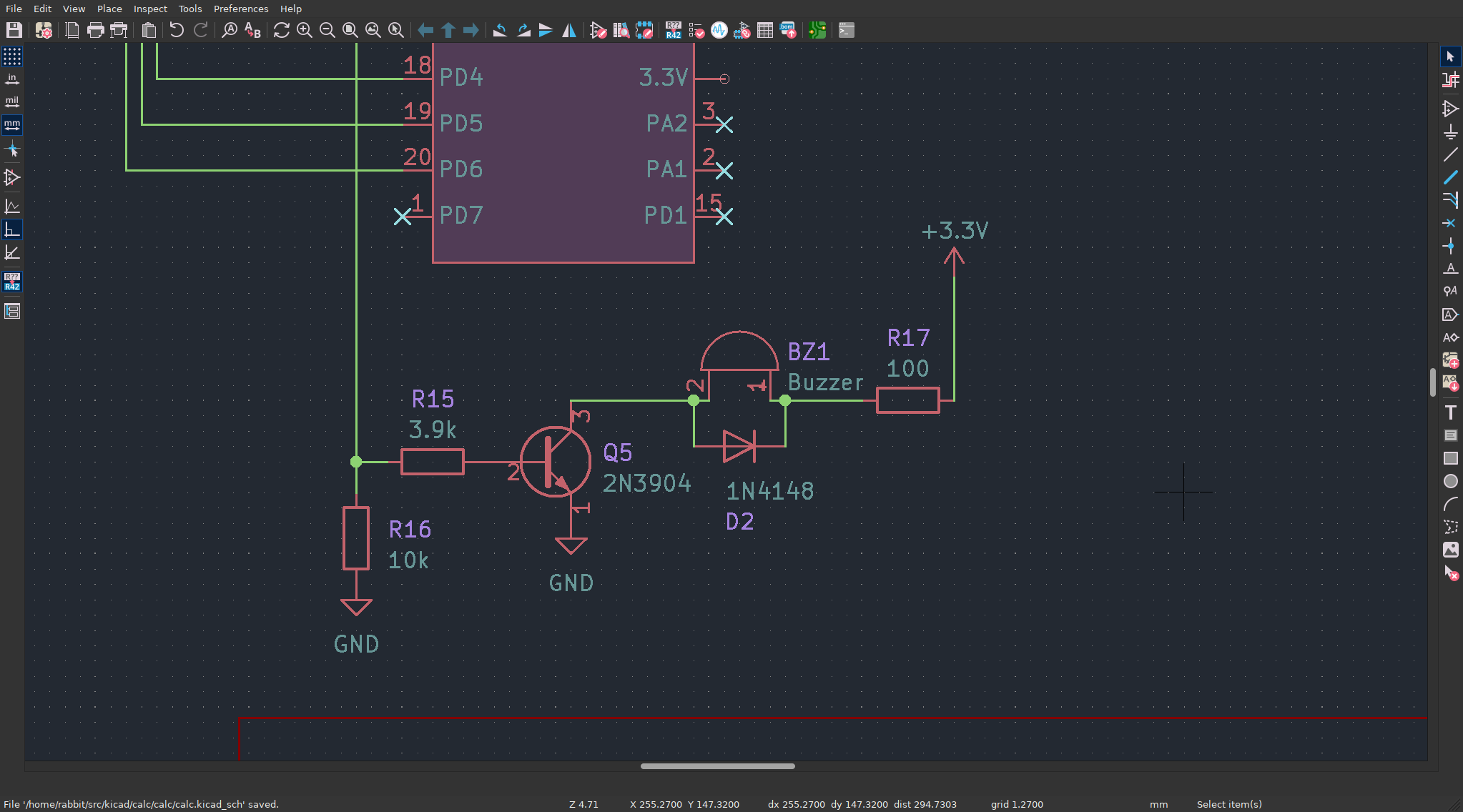
Programmer's calculator (buzzer)
A new peripheral for the calculator - a passive buzzer.
Calculation
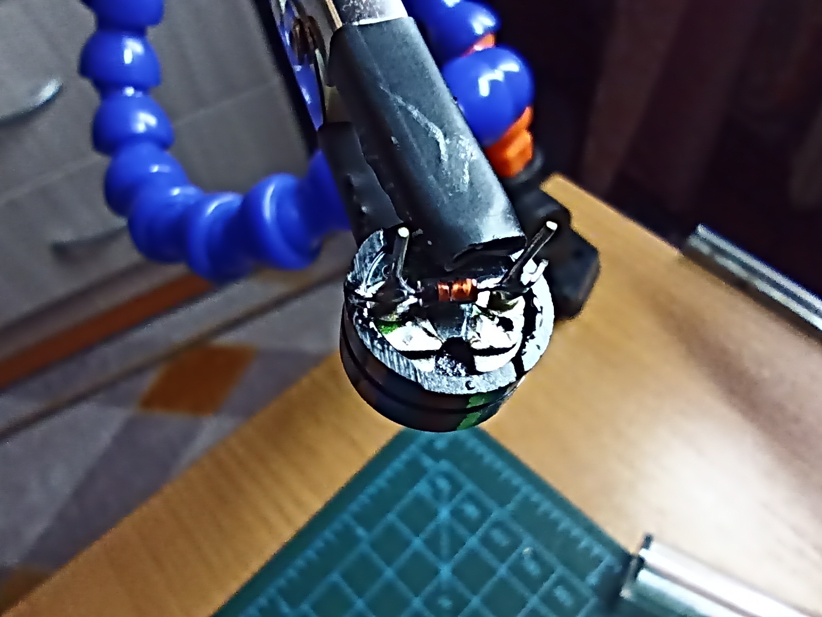
A passive buzzer with a coil resistance of 16 from an Arduino kit is used. Here’s how it looks with a soldered diode. The diode is necessary because this is an electromagnetic buzzer, not a piezo one - though even piezo buzzers might need one since they generate electricity when deformed (think of piezo lighters).
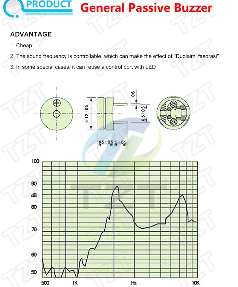
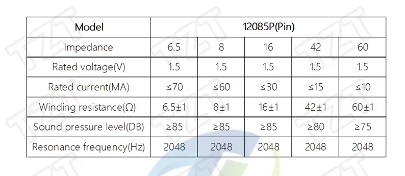
Let’s take a look at the buzzer’s specifications from TZT:
Determining the value of . The allowable current is , Assuming the average voltage across the buzzer coil is zero, we get
Let’s check the parameters of the 2N3904 transistor:
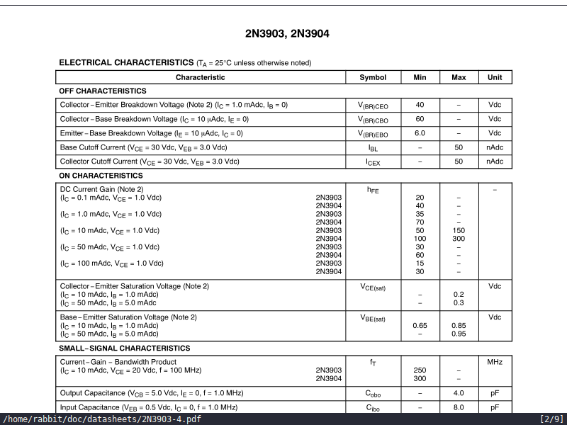
Assuming , we calculate:
Since the collector current is already limited, it’s fine even if we take the minimum . Thus, the base current .
From this, we derive:
As for , it's pull-down resistor with a sufficiently high value. Alternatively, such a resistor could simply be enabled on the CH32V003 pin.