Programmer's calculator
This is a very simple thing - a desktop calculator for operations in different number systems.
It is imagined as having a few lines of display, a lithium battery, and a keyboard with a small number of keys.
Keyboard
I will use Rue Mohr's scanless keyboard design http://ruemohr.org/~ircjunk/tutorials/elex/scanlessKeyboard/scanlessKeyboard.html .
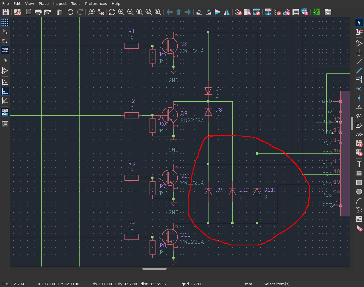
Here is draft of the schematics:
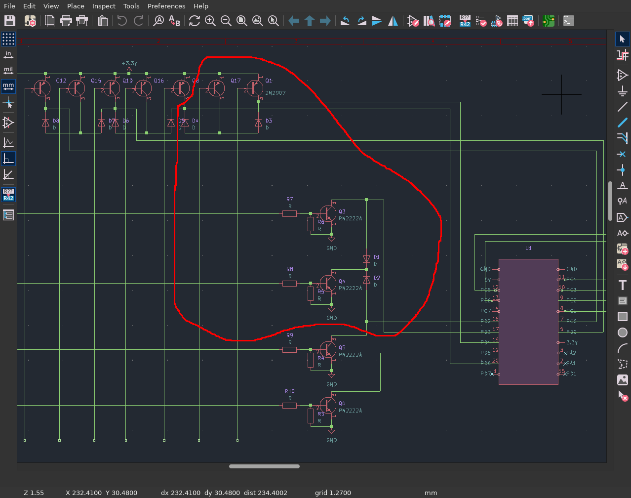
I use the highlighted fragment to determine the resistor ratings.
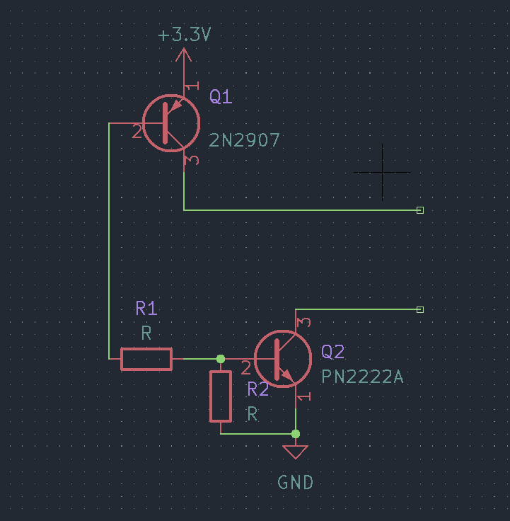
Let me speculate: the CE current of transistor Q1 is determined by the resistance of the 45k pull-down resistor of the controller pin (not shown in the schematic):
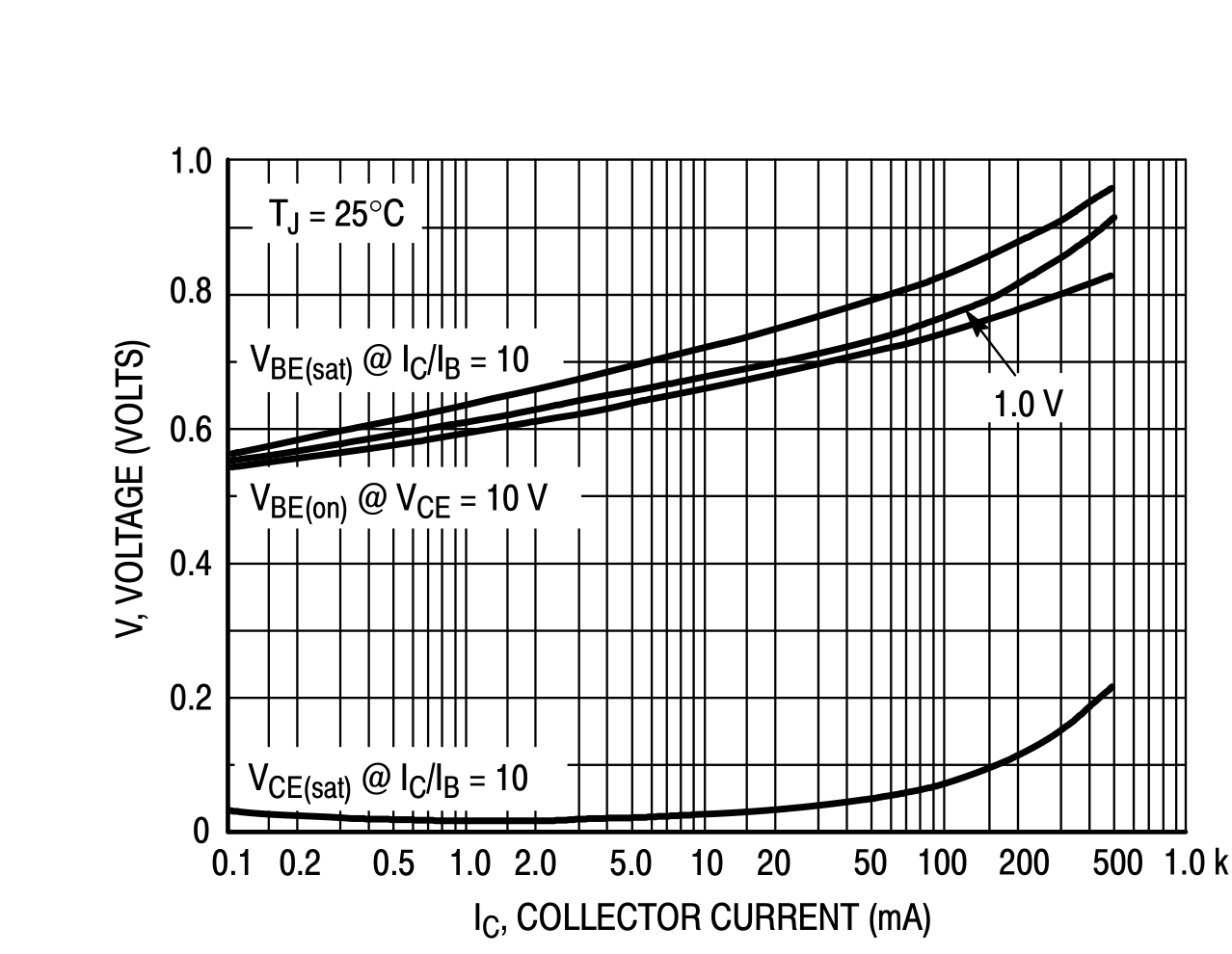
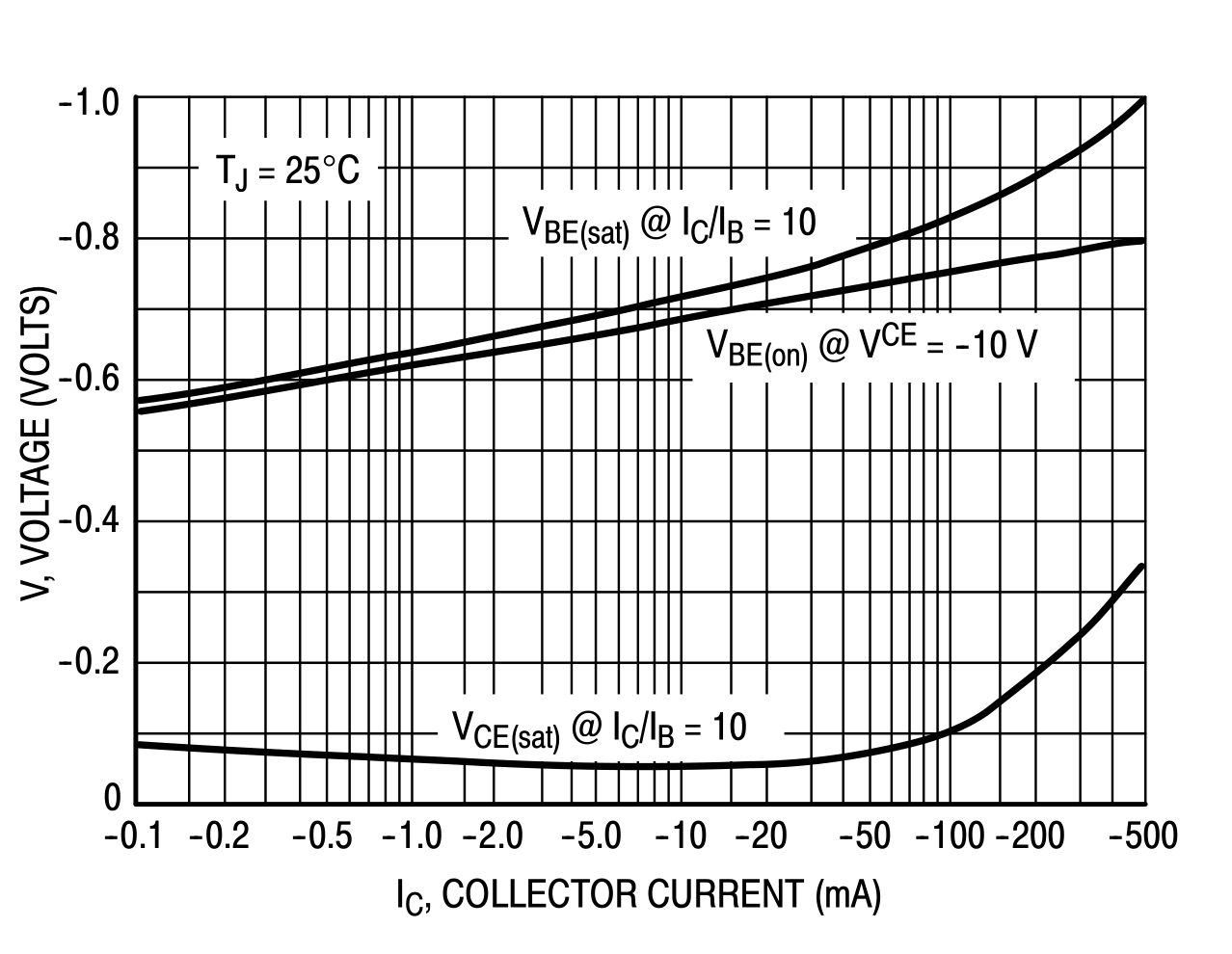
Based on the datasheet chart, I determine that to go into saturation mode, it is enough to provide 0.6V voltage at the base. The same applies to transistor Q2.
Hence the voltage drop across resistor R1:
As can be seen from the same graphs, the base-emitter saturation current is 10 times less than the :
I choose the resistor R2 arbitrarily 10k - anyway the voltage drop on it equals .
You cannot move higher because of the danger of getting too little current, on the other hand a high current will have no effect. So I choose the value of 20k.
The current through resistor R1 is actually the same as predicted

Rue Mohr's <https://twitter.com/RueNahcMohr> told me to change the circuit so as to get a "keystroke detection circuit":