FPGA and a rotary encoder
How to program an FPGA to work with such simple input / output devices as a rotation angle sensor and LED indicator.
When I studied FPGA in the begining, I really wanted to have some kind of visible response to my program. The built-in RGB LED became old quickly, in particular due to my poor sense of color :wink:, so the 17-segment indicator was the first external device.
Indicator
I found an indicator with a common cathode, 17 resistors of 100 Ohms each based on the fact that on the green LED segment the voltage drops is about 2.4 Volts, the FPGA output has 3.3 Volts, so the current is .
So even all segments lighted will not lead to overcurrent.
Here is a simple indicator module. A1, A2, ... - symbolic names of indicator segments according to the documentation.
/*****************/
/* 0-15 on 17led */
/*****************/
module Display16(
    input wire [3:0] i_x,
    output reg [16:0] o_led);

    localparam A1 =  1 << 4;
    localparam A2 =  1 << 5;
    localparam B  =  1 << 6;
    localparam C  =  1 << 7;
    localparam D1 =  1 << 1;
    localparam D2 =  1 << 0;
    localparam E  =  1 << 2;
    localparam F  =  1 << 3;
    localparam G1 =  1 << 11;
    localparam G2 =  1 << 15;
    localparam H  =  1 << 12;
    localparam J  =  1 << 13;
    localparam K  =  1 << 14;
    localparam L  =  1 <<  8;
    localparam M  =  1 <<  9;
    localparam N  =  1 << 10;
    localparam DP =  1 << 16;


    always @(i_x) begin
      case (i_x)
        4'h0 : o_led = A1 + A2 + B + C + D2 + D1 + E + F; // 0
        4'h1 : o_led = K + B + C; // 1
        4'h2 : o_led = A1 + A2 + B + G2 + N + D1 + D2; // 2
        4'h3 : o_led = A1 + A2 + B + G2 + C + D2 + D1; // 3
        4'h4 : o_led = F + G1 + G2 + B + C; // 4
        4'h5 : o_led = A1 + A2 + F + G1 + G2 + C + D1 + D2; // 5
        4'h6 : o_led = A1 + A2 + F + G1 + G2 + C + D2 + D1 + E; // 6
        4'h7 : o_led = A1 + A2 + K + M; // 7
        4'h8 : o_led = A1 + A2 + B + C + D2 + D1 + E + F + G1 + G2; // 8
        4'h9 : o_led = A1 + A2 + B + C + D2 + D1 + F + G1 + G2; // 9
        4'ha : o_led = A1 + A2 + B + C + E + F + G1 + G2; // A
        4'hb : o_led = A1 + J + G2 + C + D2 + D1 + E + F + G1; // B
        4'hc : o_led = D2 + D1 + E + F + A1 + A2; // C
        4'hd : o_led = A1 + A2 + B + C + D2 + D1 + M + J; // D
        4'he : o_led = A1 + A2 + G1 + D2 + D1 + E + F; // E
        4'hf : o_led = E + F + A1 + A2 + G1; // F
      endcase
    end

endmodule
// vim: expandtab:sw=4:ts=4:
Combinatorial circuit and non-clocked output register. This was my very first module on Verilog:)
This is what it turns into after compilation:
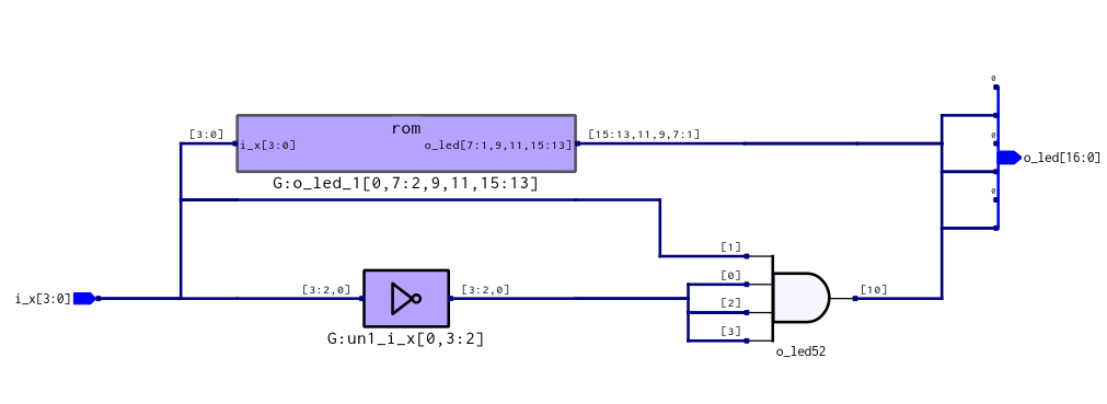
13 LUT4 of 1152 were spent.
Contact bounce
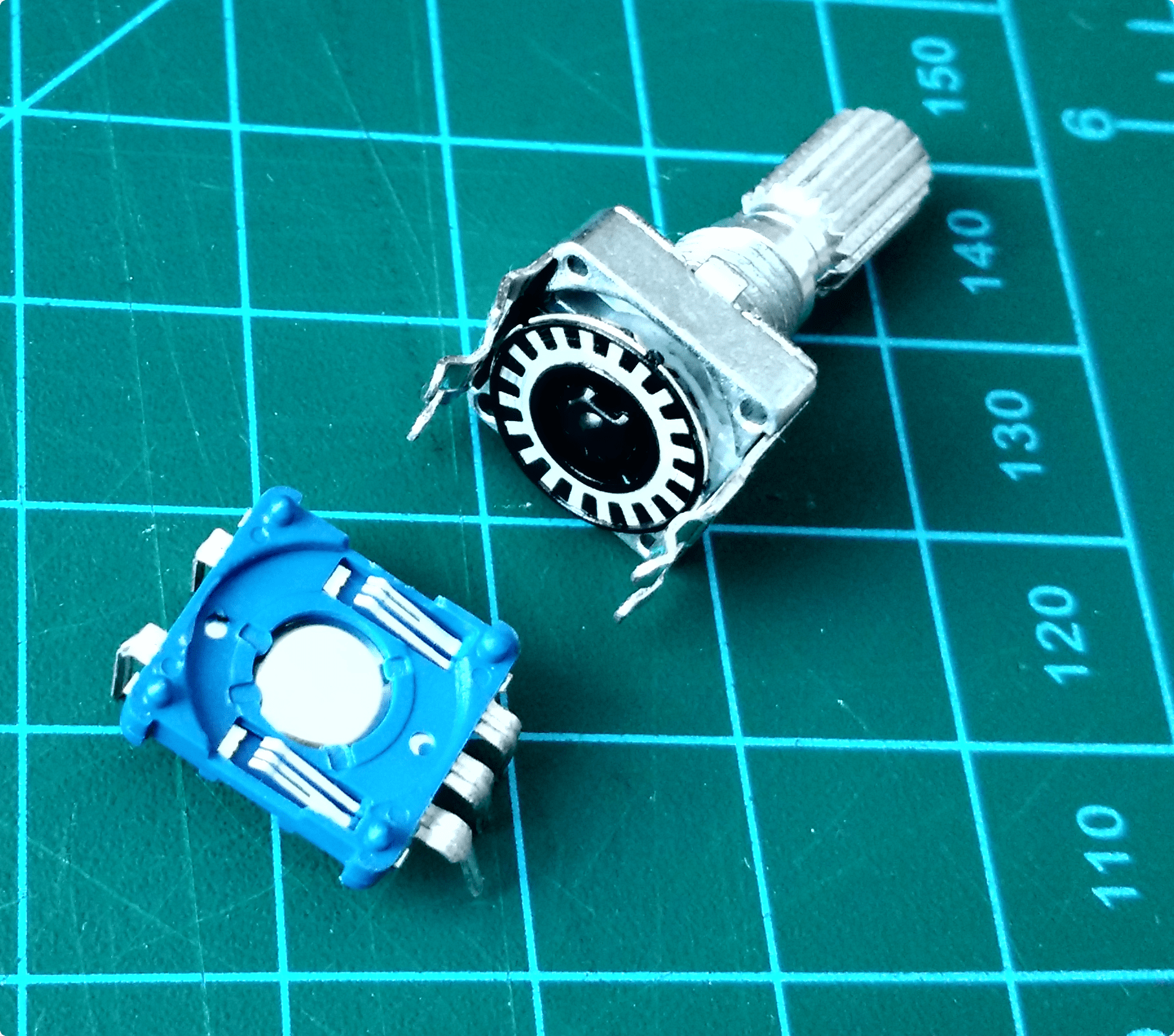
My rotary encoder has a very noisy electrical design:
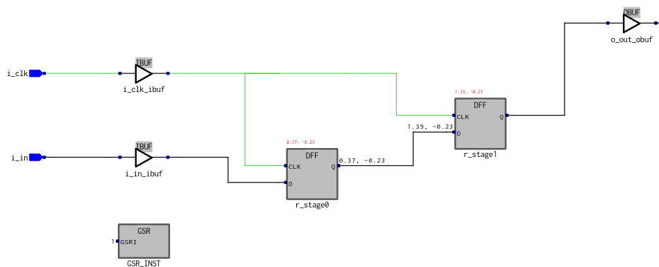
First, we eliminate the metastability at the inputs, two flipflops are enough.
`default_nettype none
 module metastab(
     input wire i_clk,
     input wire i_in,
     output wire o_out);

     reg r_stage0;
     reg r_stage1;

     always @(posedge i_clk) begin
         {r_stage1, r_stage0} = {r_stage0, i_in};
     end

     assign o_out = r_stage1;
 endmodule
 // vim: expandtab:sw=4 ts=4
And the code really turns into two flip flops:)
We got rid of metastability, but this only guarantees us that the signal will be stable during the clock pulse and does not relieve spurious responses of the contacts.
One of the options for suppressing contact bounce is to use an RC filter in combination with a Schmitt trigger:

A low-pass filter smooths out high-frequency noise, and Schmitt's trigger is needed in order to correctly process the input signal in the range from 0.8 to 2 Volts. However, as noted by Rue:

He also suggested using a software implementation of the RC filter and Schmitt trigger:
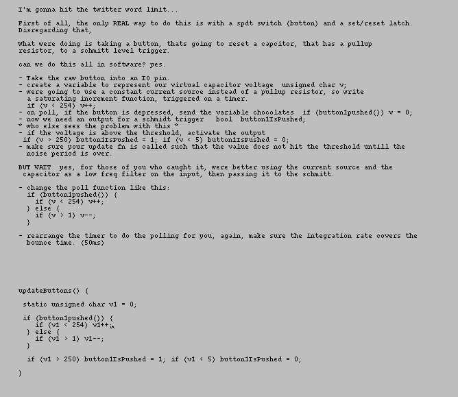
Almost all of this migrated to code I eventually used. Some notes:
- I did not change the integration frequency, but used the standard 24 MHz;
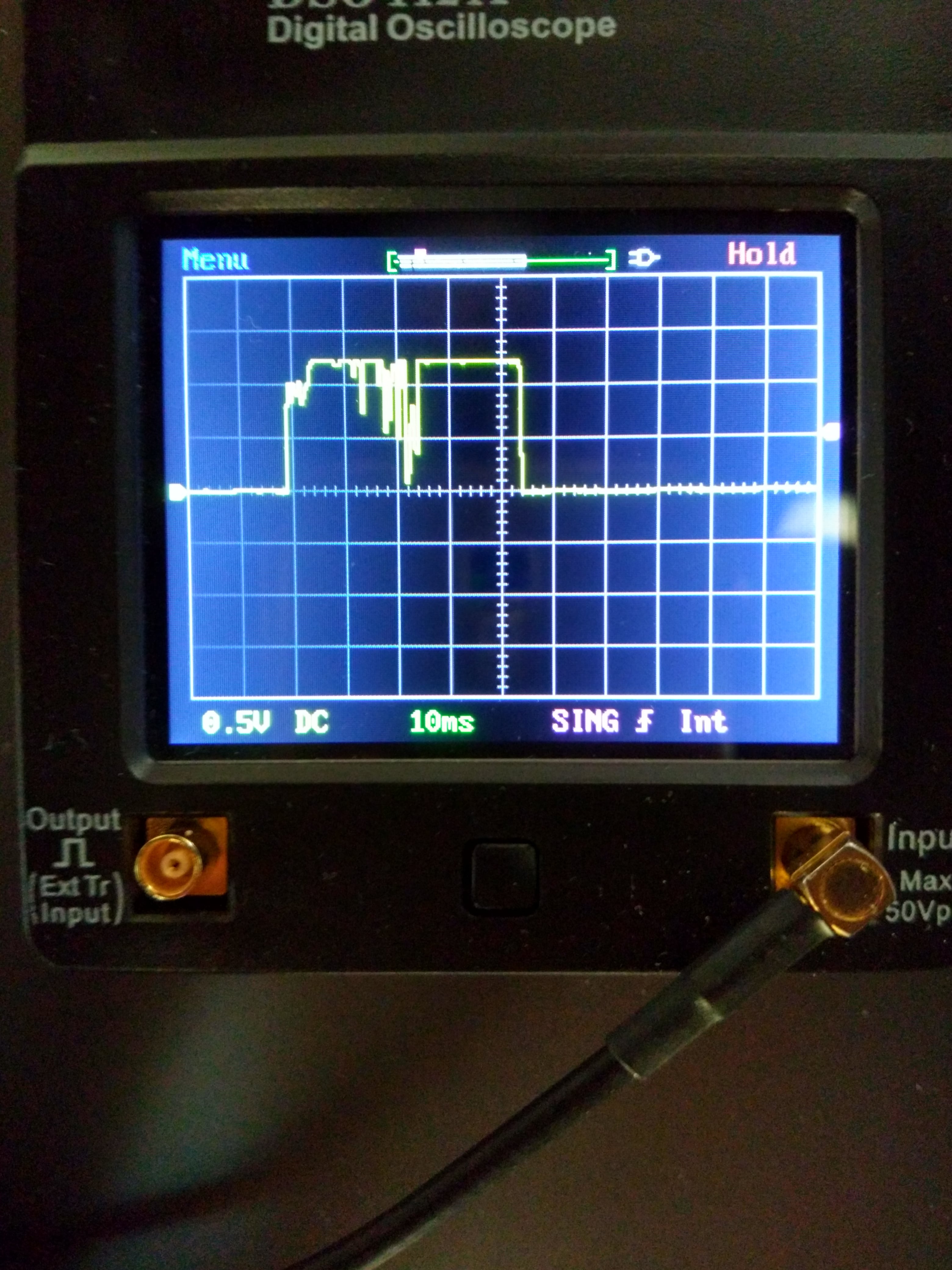
- the integration period was chosen to be 5ms since I achieved values close to this by very quickly rotating the handle of the sensor observing the signal on the oscilloscope screen;
- I did not see the point of counting to 254 and to 1 (
if (v1 < 254) v1++) and then compare with 250 and 5; - due to the desire to save LUTs, I rather roughly adjusted all constants to powers of two;
- since I have LUT4, then w_isLow, for example, will consist of two cascaded LUT4s, the output of the first of which will be one of the inputs of the second, therefore only 7 input bits can be used. This explains the constant 7 in localparam IGNORE_BITS
`default_nettype none
 module Debounce5ms(
         input wire i_clk,
         input wire i_btn,
         output wire o_btn);
     /* 24MHz ~ 42e-9s, for 5ms we need *1e5 ~ 2^16
      * for Schmitt part we can ignore lower ~2^9 */
     localparam TOTAL_BITS = 16;
     localparam HI_BIT = TOTAL_BITS - 1;
     localparam IGNORE_BITS = TOTAL_BITS - 7;

     // test bounds
     reg [HI_BIT:0]r_counter;
     wire w_isLow;
     wire w_isHigh;
     assign w_isLow = !(|r_counter[HI_BIT:IGNORE_BITS]);
     assign w_isHigh = &r_counter[HI_BIT:IGNORE_BITS];

     // Capacitor
     always @(posedge i_clk) begin
         if (i_btn) begin
             if (!w_isHigh) begin
                 r_counter <= r_counter + 1'b1;
             end
         end else begin
             if (!w_isLow) begin
                 r_counter <= r_counter - 1'b1;
             end
         end
     end

     // Schmitt
     reg r_debouncedBtn;
     always @(posedge i_clk) begin
         if (w_isLow) begin
             r_debouncedBtn <= 0;
         end
         if (w_isHigh) begin
             r_debouncedBtn <= 1;
         end
     end
     assign o_btn = r_debouncedBtn;
 endmodule
 // vim: expandtab:ts=4 sw=4
You can make sure that the generated elements are connected in exactly this way:
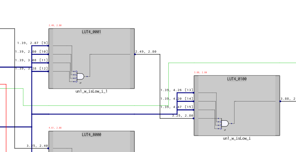
By this moment, we have reached the stage when the complexity of the generated circuit has grown so much that it makes no sense to show it here.
Decimal counter
This is a very simple module, for some reason I even provided the carry, although for this system with just one indicator, this is not necessary. In addition, the boundary conditions and are checked loosely, this helps to get rid of the impossible states of the decimal counter, which is important in the absence of a RESET signal.
I did not bother with RESET because:
- in my board it is connected to one of the two buttons, which greatly interferes with debugging;
- I still have the ambiguity of which is more correct: synchronous or asynchronous RESET with the possible presence of a special dedicated line to each flipflop.
`default_nettype none
 module DecadeCounter(
         input wire i_clk,
         input wire i_inc,
         input wire i_dec,
         output wire [3:0]o_cnt,
         output wire o_carry);
     reg [3:0]r_cnt;
     reg r_carry;

     always @(posedge i_clk) begin
         if (i_inc) begin
             if (r_cnt >= 'd9) begin
                 r_cnt <= 0;
                 r_carry <= ~r_carry;
             end else begin
                 r_cnt <= r_cnt + 1'b1;
             end
         end
         if (i_dec) begin
             if (r_cnt == 'd0 || r_cnt > 'd9) begin
                 r_cnt <= 'd9;
                 r_carry <= ~r_carry;
             end else begin
                 r_cnt <= r_cnt - 1'b1;
             end
         end
     end
     assign o_cnt = r_cnt;
     assign o_carry = r_carry;

 endmodule
 // vim: expandtab:sw=4 ts=4
Single vibrator
The auxiliary module, which gives out a pulse of a fixed duration when the positive edge of the input signal is detected. It may not be necessary, but all my attempts to use the posedge input_signal led to a compiler hysteria, which for some reason decided that I want to create another clock
`default_nettype none
module SingleTick(
    input wire i_clk,
    input wire i_btn,
    output wire o_btn);
    reg r_oldstate;
    reg r_btn;

    always @(posedge i_clk) begin
        r_oldstate <= i_btn;
        r_btn <= i_btn && (i_btn != r_oldstate);
    end

    assign o_btn = r_btn;
endmodule
// vim: expandtab:sw=4 ts=4
Rotary encoder
How the sensor works is described in article. And here I will give two pictures from there, by which it becomes clear what I'm trying to do in the program:

In short, the state of {1, 1} is significant for me, and I determine the direction of rotation depending on previous state.
`default_nettype none
module Rotary2018(input wire i_clk,
            input wire i_btn_a_,
            input wire i_btn_b_,
            output wire o_cw,
            output wire o_ccw);

        /* (meta)stablize buttons */
        wire w_btn_a;
        wire w_btn_b;
        metastab mbtn0(i_clk, ~i_btn_a_, w_btn_a);
        metastab mbtn1(i_clk, ~i_btn_b_, w_btn_b);

        /* debounce buttons */
        wire w_dbtn_a;
        wire w_dbtn_b;
        Debounce5ms dbtn0(i_clk, w_btn_a, w_dbtn_a);
        Debounce5ms dbtn1(i_clk, w_btn_b, w_dbtn_b);

        reg r_cw;
        reg r_ccw;
        reg r_a;
        reg r_b;

        // is {1, 1}
        wire w_is_signal_state;
        assign w_is_signal_state = w_dbtn_a & w_dbtn_b;

        always @(posedge i_clk) begin
            r_a <= w_dbtn_a;
            r_b <= w_dbtn_b;
            // signal only when change to {1, 1}
            if (w_is_signal_state) begin
                if (!(r_a & r_b)) begin
                    r_cw <= r_a;
                    r_ccw <= r_b;
                end
            end else begin
                r_cw <= 0;
                r_ccw <= 0;
            end
        end
        SingleTick st0(i_clk, r_cw, o_cw);
        SingleTick st1(i_clk, r_ccw, o_ccw);
endmodule
// vim: expandtab:sw=4 ts=4
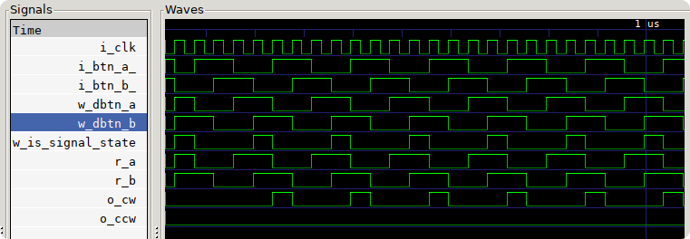
A small graph of clockwise rotation detection:
All together
`default_nettype none
module main(input wire i_clk,
            input wire i_btn_a_,
            input wire i_btn_b_,
            output wire [16:0] o_led);

        wire [3:0] w_counter;
        /* verilator lint_off UNUSED */
        wire w_carry;
        /* verilator lint_on UNUSED */

        /* rotary */
        wire w_cw;
        wire w_ccw;
        Rotary2018 rot0(i_clk, ~i_btn_a_, ~i_btn_b_, w_cw, w_ccw);

        DecadeCounter dcnt0(i_clk, w_cw, w_ccw, w_counter, w_carry);

        // display
        Display16 disp0(w_counter, o_led);

endmodule
// vim: expandtab:sw=4 ts=4
How does this system work:
Conclusion
In general, I liked how you can describe programmatically and then get a working device in the hardware. Yes, there are many pitfalls, yes, you need to change the programmer’s thinking in a different way, but it’s funny and interesting :)