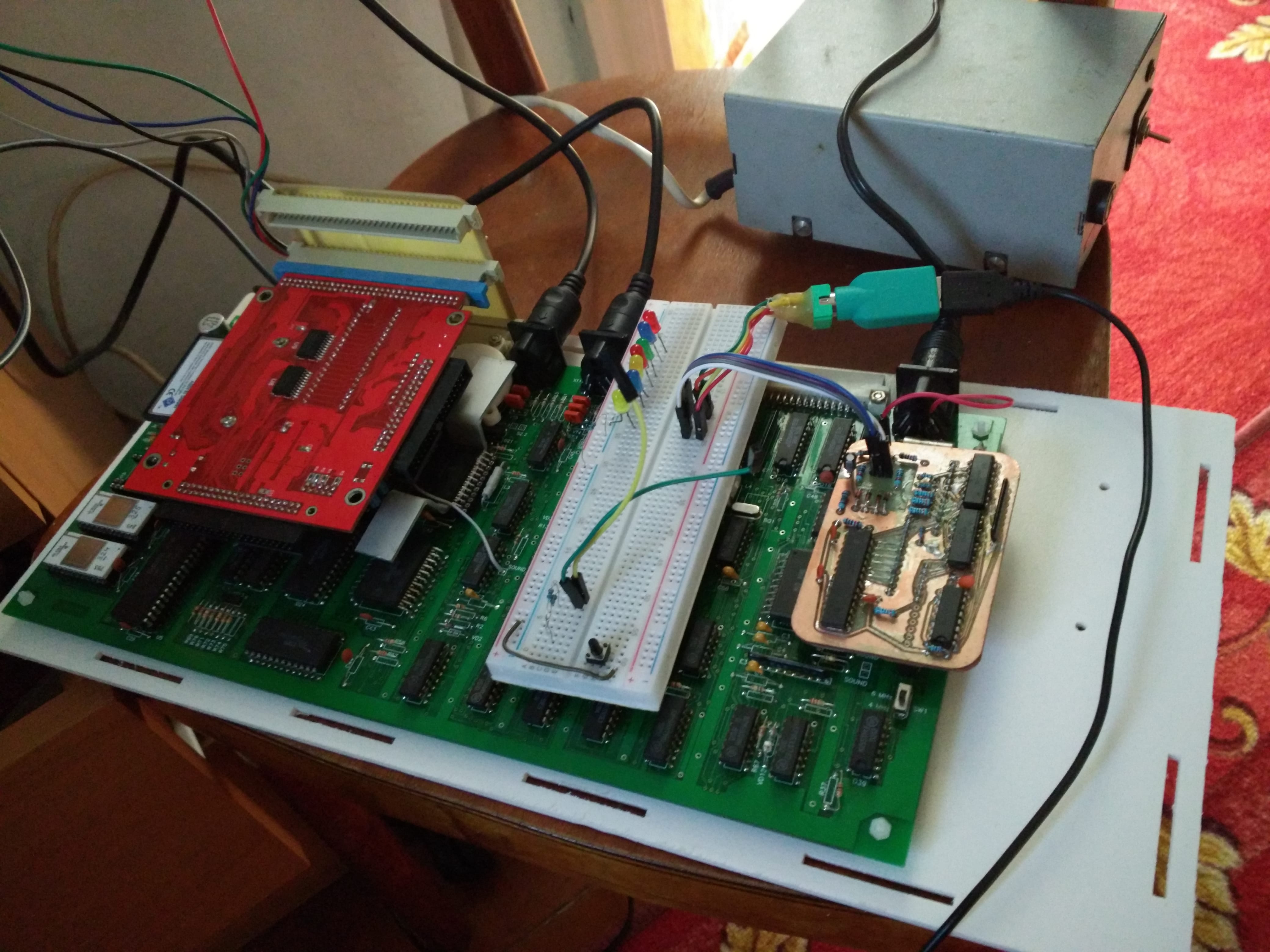
DIY PS/2 keyboard adapter
On the one hand, the adapter accepts keystrokes from the standard PS / 2 keyboard, and on the other hand, manipulates the input lines of the 1801VP1-014 chip by pretending to be a matrix of keys. The number of AtMega8 outputs is increased using a shift register. The firmware is written in the Forth dialect muforth
PS/2
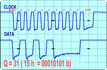
I will not repeat here the full descriptions of the PS/2 protocol and electrical connection, as well as the key scancodes. This can be seen here and also here. Two pictures to remind:
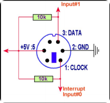
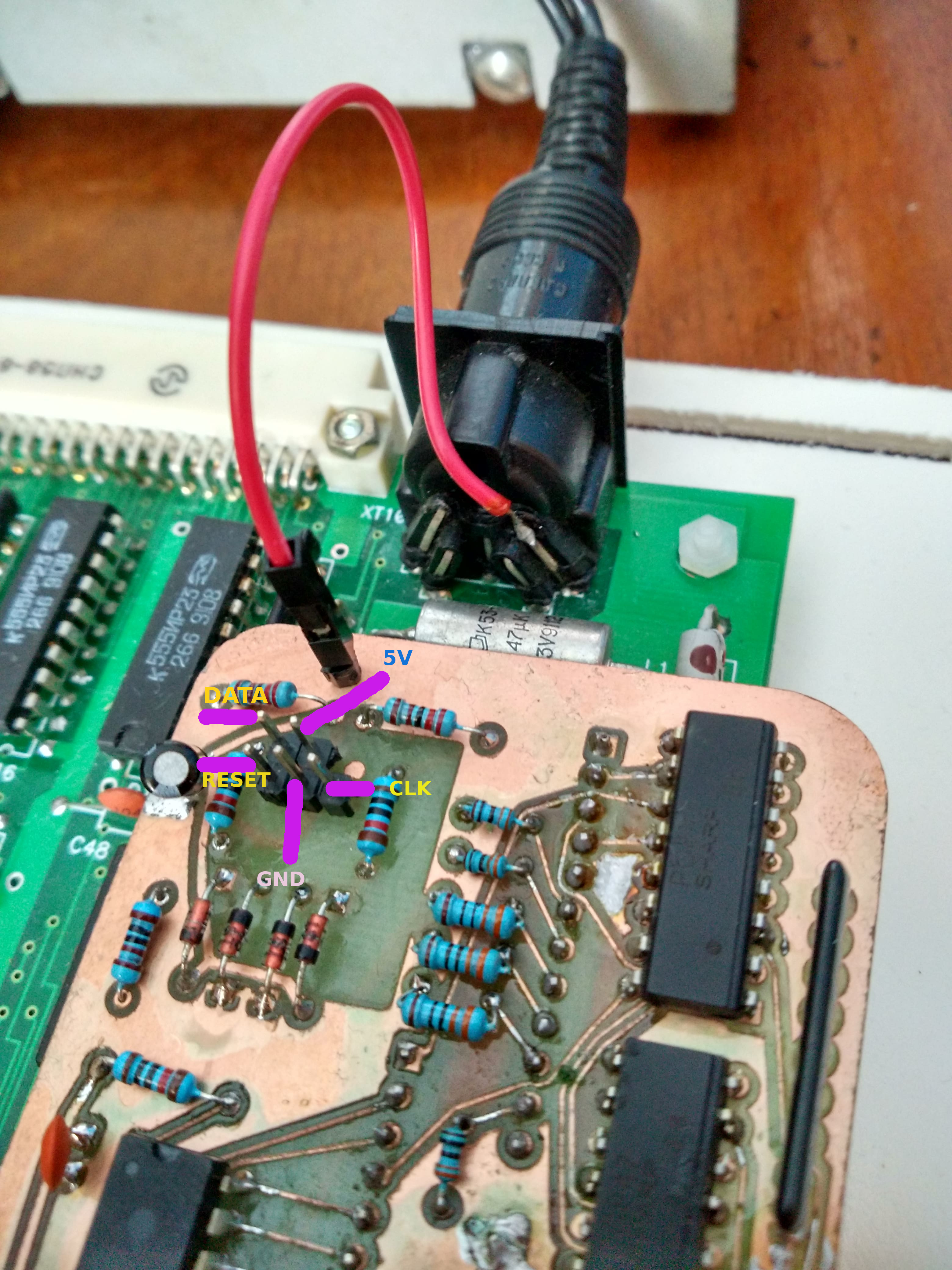
This is how I connect the PS/2:
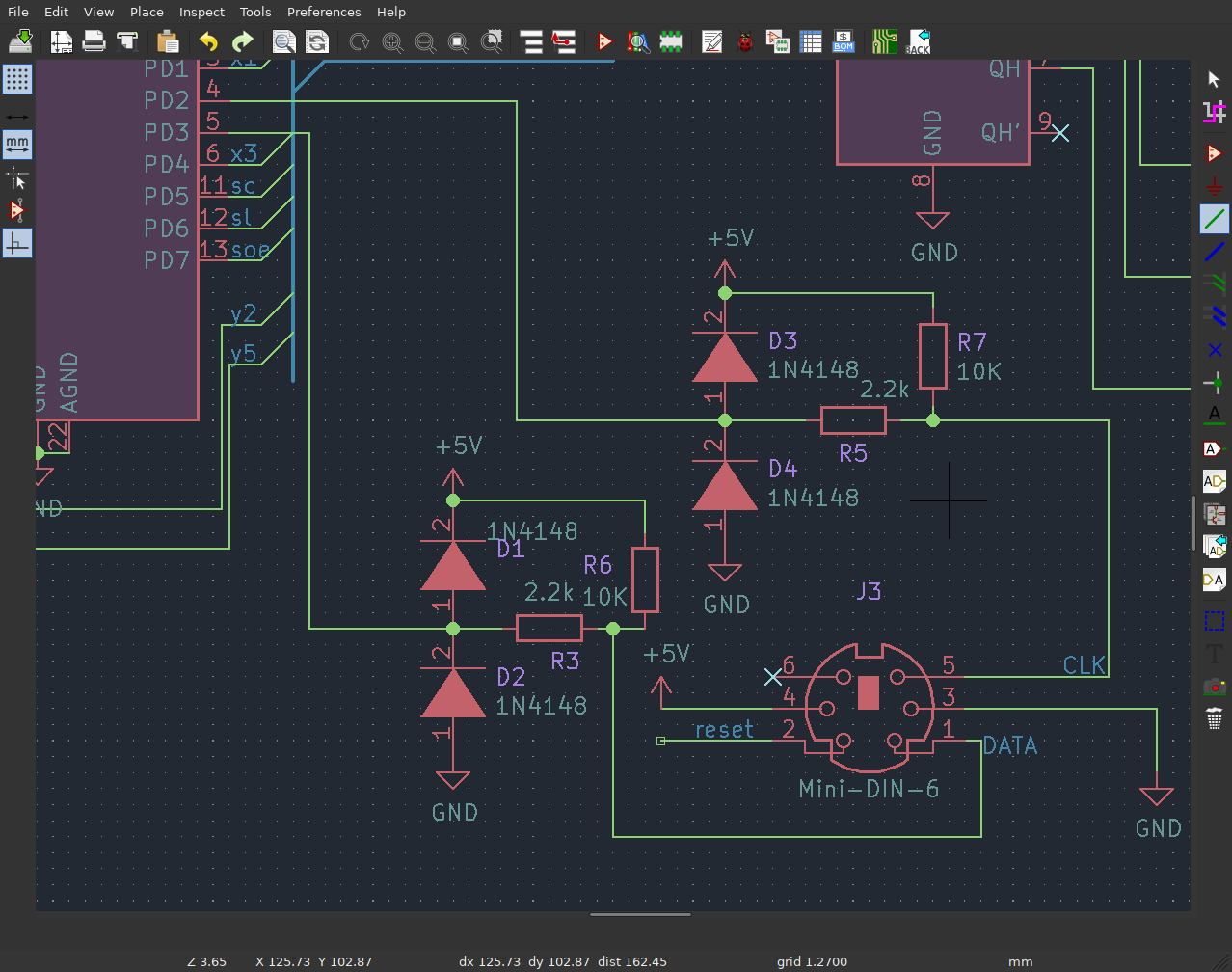
R7 and R6 provide the formation of signals for outputs with an open collector at the keyboard, circuits with diodes (D1, D2, D3 и D4) and resistors R3 и R5 form a simple protection from static electricity. D2 (INT0) is connected to the CLK line, so an interrupt is used to synchronize with the keyboard when reading data. D3 is used as the DATA.
Power will have to be taken directly from the BK connector
INT0 is set to trigger on a fall.
%01 equ ISC00
%10 equ ISC01

code init-ps2
   ( ISC00=0, ISC01=1 -- the falling edge of INT0 generates an interrupt request)
   MCUCR h0 lds ISC00 invert h0 andi ISC01 h0 ori MCUCR h0 sts
   PS2CLK  DDRD cbi PS2CLK  PORTD cbi
   PS2DATA DDRD cbi PS2DATA PORTD cbi
   ret ;c
One of the timers is used to detect a timeout during communication with the keyboard: if a significant amount of time has passed since the last interruption on the CLK line, then I believe that a failure has occurred and I start receiving the byte from the very beginning. Start bit, parity bit and stop bit are ignored. The received byte is written to the ring buffer.
===========================================================================
 INT0 handler. Read data. Ignore start, parity and stop bits.
 After receiving BITS-PER-PACKET bits decode byte.
===========================================================================
code INT0-handler
    r0 push x pushw h0 push
    r0 clr

    -- PS2 wait not expired
    "ff tl ldi TIFR h0 in
    TOV0 h0 sbrs always tl clr 1 TOV0 << h0 ldi TIFR h0 out then
    -- tl = 0  -- PS2 timeout
    -- tl = ff -- no PS2 timeout

    -- X = bitcount addr
    bit-count >hilo xl ldi xh ldi

    -- timeout?
    tl tst .Z if BITS-PER-PACKET h0 ldi x@ h0 st then

    -- reset timeout timer
    256 PS2-WAIT-PERIOD - h0 ldi
    TCNT0 h0 out

    -- read bit if 2 < bitcount < BITS-PER-PACKET
    x@ h0 ld 3 h0 cpi      -- C = 0 if bit-count >= 3
                           -- C = 1 if bit-count < 3
      .C not if
            BITS-PER-PACKET h0 cpi -- C = 0 if bit-count >= BITS-PER-PACKET
                                   -- C = 1 if bit-count < BITS-PER-PACKET
             .C if -- read bit. Note bit C is set now!
                PS2DATA PIND sbis clc
                byte-read tl lds tl ror byte-read tl sts
            then
       then
    x@ h0 ld h0 dec -- h0 = bit-count 1-
    .Z if
              -- input-write
              input-wptr tl lds tl th mov th inc input-wptr th sts  -- input-wptr++
              BUFFER-LEN 1 - tl andi                                -- mask ptr
              input-buffer >hilo xl ldi xh ldi
              tl xl add r0 xh adc
              byte-read tl lds x@ tl st
              BITS-PER-PACKET h0 ldi
           then
    bit-count h0 sts

    h0 pop x popw r0 pop ret ;c
The 32-byte ring buffer is very simple: the pointers for reading and writing are increased to overflow a 16-bit word, and a mask is used for reading / writing. The word for writing to the buffer is commented out because the assembler version is used in the procedure for processing the keyboard interrupt.
===========================================================================
 Simple ring buffer.
 Uses two free pointers, which masked during access only.
===========================================================================
32 equ BUFFER-LEN   -- Note: need 10 bytes for PrtScreen press/release
BUFFER-LEN var input-buffer
1 var input-rptr
1 var input-wptr
: init-input-buffer 0 dup input-rptr c! input-wptr c! ;
code input-mask ( n - n) BUFFER-LEN 1- tl andi ret ;c
: input-empty? ( - f) input-wptr c@ input-rptr c@ = ;

( return ptr value and increment ptr)
: advance-ptr ( a - n) dup c@ swap over 1+ swap c! ;
comment XX : input-write (  b) input-wptr advance-ptr input-mask input-buffer + c! ; XX
: input-read ( - b) input-rptr advance-ptr input-mask input-buffer + c@ ;
Matrix of the keys
Matrix has 10 columns , 8 rows ( is always connected to ground) and few service signals. have pullup resistors 22K, - pulldown resistors 180K. The service lines, besides STOP, have pullup resistors 3.3K.
In the initial state, the corresponding lines of the 1801VP1-014 work as inputs, the resitors provide a high level at and a low level at . When a key is pressed, the following occurs:
- gets a high level from the resulting 22K/180K divisor.
- switches to low output mode.
- gets low.
What do I need for electrical simulation of the matrix?
- is always in input mode, so you don’t have to worry about current-limiting resistors
- There is a pullup resistor, so I may not apply a high level, but just go into a high impedance state.
- work both input and output, so I need to limit the current.
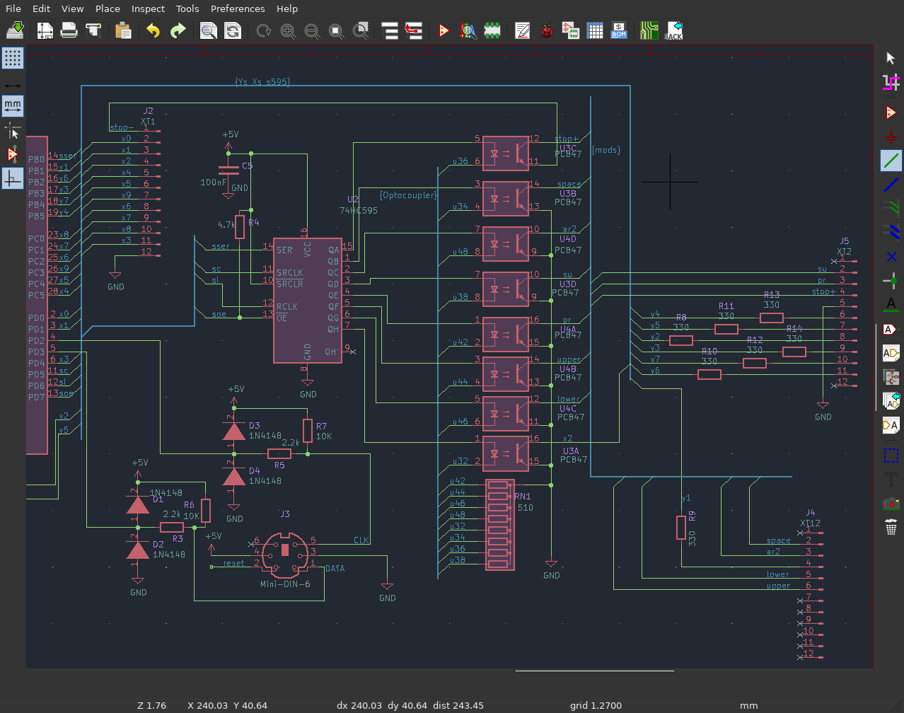
The lines (except ) are connected directly to the outputs of the microcontroller, the lines are connected through the current-limiting resistors R8-R14. The remaining signal lines and are connected to the shift register via optocouplers due to exhaustion of AtMega8 pins.Technically, optocouplers are not necessary, well, except for the STOP lines, however they were at hand :).
и line management:
===========================================================================
 Manipulate bk input lines
 X lines is switched between input and output. PortX alwayse quals 0.
 Y lines is switched between 0 and 1. DdrY is always output.

 X connects to input with 22k pullup so no need for current limiting (5/22e3 = 0.227mA).
 Y may be connected to the GND through open collector so it's better to
 use resistors. Max 200mA for all 11 pins. 200mA/11 = 18mA per pin,
 5/18e-3 = 275 Ohm min.

 -- input lines
 X0-9       = 9 pins (-x2)
 PS2 (data/clock) = 2 pins

-- output lines
 Y1-7        = 7 pins
 su + ar2 + zagl + str + pr + space + stop + x2 = 4 pins 74HC595 (7)

 total: 23 pins

 PS pins   = 2 x 10k
 Y1-7 pins = 7 x 330
 74HC595 pins = no resistors
 X0-9 = no resistors

===========================================================================

===========================================================================
 x0 - d0, x1 - d1, x3 - d4
 x4 - c5, x5 - c4, x6 - c2, x7 - c1, x8 - c0, x9 - c3
===========================================================================
code x3-3dstate
   4 DDRD cbi ret ;c
code x3-0
   4 DDRD sbi ret ;c

code y1-1
  1 PORTB sbi ret ;c
code y1-0
  1 PORTB cbi ret ;c

Transcoding
It all starts with a state machine, going over the edge XXX simulates pressing STOP, going over the edges scancode leads to checking for special keys and then reading the command from one of the function tables. The command is a bit set, which indicates which lines need to be manipulated and how.
===========================================================================
 Normal key pressed
===========================================================================
: NORMAL ( b)
   dup "f0 = if drop 2release  ^ then
   dup "e0 = if drop 2extended ^ then
   dup "e1 = if drop 2pause    ^ then

   dup normal-modifiers? if drop ^ then
   dup normal-quirks? if drop ^ then

   .ifdef DEBUG "c log! .then
   call-decode ;

===========================================================================
 Normal key released
===========================================================================
: RELEASE ( b)
   dup "f0 = if drop 2normal ^ then
   dup "e0 = if drop 2normal ^ then

   dup release-modifiers? if drop 2normal ^ then
   dup release-quirks? if drop 2normal ^ then

   .ifdef DEBUG "d log! .then
   call-release-decode 2normal ;

===========================================================================
 Extended key pressed
===========================================================================
: EXTENDED ( b)
   dup "f0 = if drop 2rel-ext ^ then
   dup "e0 = if drop 2normal ^ then

   dup extended-modifiers? if drop 2normal ^ then
   dup extended-quirks? if drop 2normal ^ then

   .ifdef DEBUG "e log! .then
   call-decode 2normal ;

===========================================================================
 Extended key released
===========================================================================
: REL-EXT ( b)
   dup "f0 = if drop 2normal ^ then
   dup "e0 = if drop 2normal ^ then

   dup ext-release-modifiers? if drop 2normal ^ then
   dup ext-release-quirks? if drop 2normal ^ then

   .ifdef DEBUG "f log! .then
   call-release-decode 2normal ;

===========================================================================
 Pause key pressed
===========================================================================
( Pause send next bytes: E1,14,77,E1,F0,14,F0,77
  there is no reason to store first E1 therefore we store remaining bytes)
7 equ PAUSE-CHARS-LEN
name pause-chars "14 c, "77 c, "e1 c, "f0 c, "14 c, "f0 c, "77 c, .even
: PAUSE ( b)
      ['] pause-chars pause-char-ptr c@ +
      asm{ { t z movw th clr pmz tl ld } }
      = invert if 2normal ^ then
      pause-char-ptr c@ 1+
      dup PAUSE-CHARS-LEN < if pause-char-ptr c! ^ then
      drop
      mod-stop-p send-mod mod-stop-r send-mod 2normal ;
Part of the function table:
===========================================================================
 Recode tables for x/y lines [0..ff]
===========================================================================
( normal/release lat)
name lat-normal
   ( 00            01:F9        02         03:F5         04:F3  )
   key-nop c,    key-sbr-p c, key-nop c, key-|==>-p c, key-=|=>-p c,

   ( 05:F1           06:F2        07:F12     08            09:F10 )
   key-povtor-p c, key-kt-p c,  key-nop c, key-nop c,    key-nop c,

   ( 0a:F8         0b:F6          0c:F4         0d:tab       0e:`)
   key-shag-p c, key-indsu-p c, key-|<==-p c, key-tab-p c, key-nop c,

   ( 0f         10         11:LAlt    12:LShift    13         14:LCtrl)
   key-nop c, key-nop c, key-nop c, key-nop c,   key-nop c, key-nop c,

   ( 15:q       16:1       17         18         19         1a:z)
   key-q-p c, key-1-p c, key-nop c, key-nop c, key-nop c, key-z-p c,
Downloads
- Kernel source - Forth kernel.
- Monitor source - a monitor designed to exchange commands and data on a serial line is needed for initial initialization of the Fort.
- Firmware source - main program.
- Binary firmware - compiled firmware.
Fuses: E:FF, H:DE, L:E4
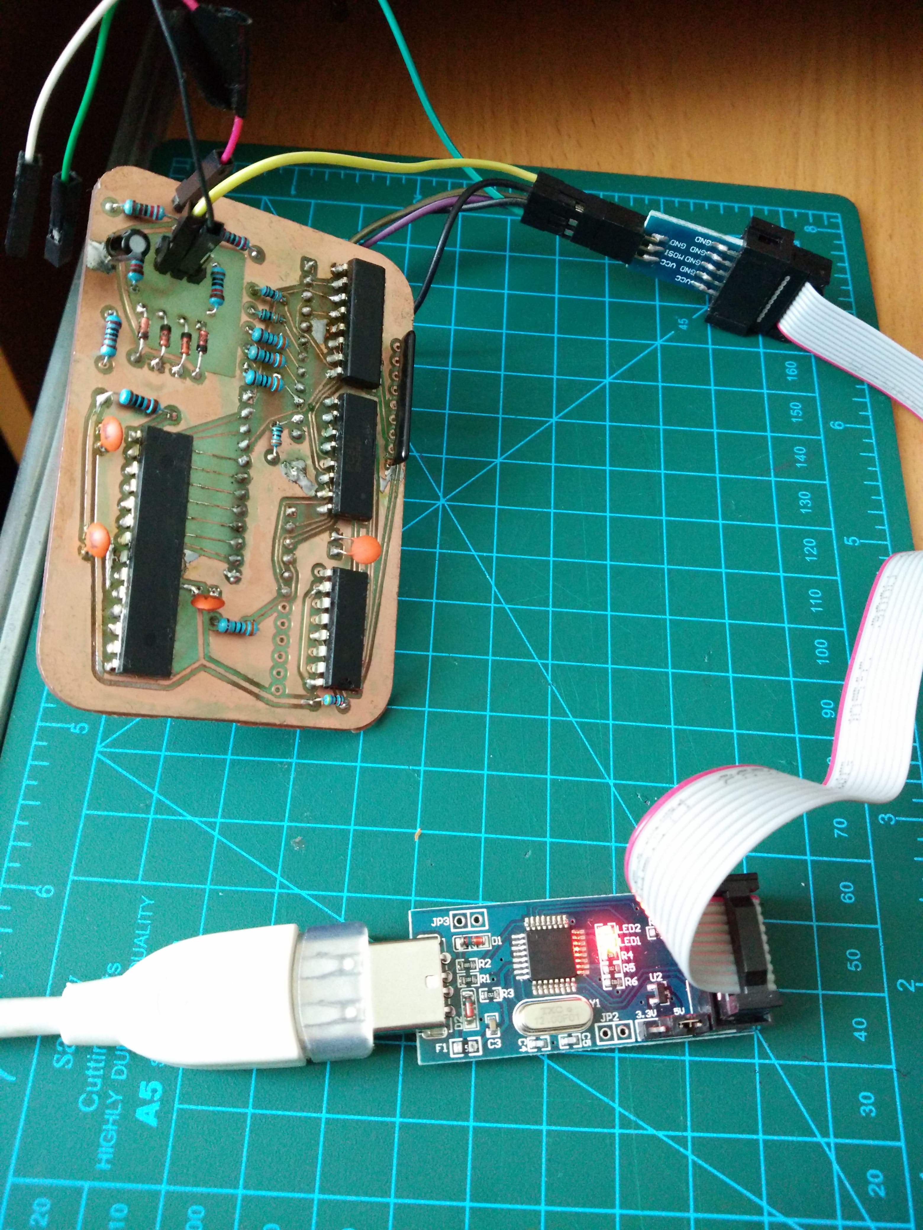
The microcontroller can be flashed directly on the board, here is the table for connecting the programmer:
| Pin | Purpose |
|---|---|
| 6 - XT2 (J5) | SCK |
| 9 - XT2 (J5) | MOSI |
| 10 - XT2 (J5) | MISO |
| 12 - XT1 (J2) | GND |
| 2 - J3 | RESET |
Key mapping
| PS/2 key | BK key |
|---|---|
| Esc | КТ |
| F1 | ПОВТ |
| F2 | КТ |
| F3 | =|=> |
| F4 | |<== |
| F5 | |==> |
| F6 | ИНДСУ |
| F7 | БЛОКРЕД |
| F8 | ШАГ |
| F9 | СБР |
| Pause | СТОП |
| App | ВС |
| Insert | ВС |
| Delete | |<== |
| Shift | ПР |
| Ctrl | СУ |
| Alt | АР2 |
| Left Win | РУС |
| Right Win | ЛАТ |
| Home | ВС+ left |
| End | ВС+ right |
| PageUp | АР2+ up |
| PageDown | АР2+ down |